
Construction on existing buildings
Rehabilitation, Maintenance, Finish-Work and Re-purposing
The use of a building is subject to many changes during its life span. It makes no difference whether it is a townhouse with a fully-developed floor plan, typical office, administrative and commercial buildings or generously designed apartment buildings. Small rooms are to be enlarged and in reverse large rooms to be subdivided, new door and window openings are created and old ones closed. In residential construction, there is often a desire to create additional rooms for children, hobbies, work, housework, guests and bathrooms. Renovating the basement and attics is an obvious choice. Older apartment buildings often no longer meet today’s requirements for apartment size and room layout.
All these measures require walls that are solidly constructed.
Independent of the construction type, requirements are set in DIN 4103-1 to guarantee the stability of the walls for usage dependent demands. These are typical impact and console loads. Non-load-bearing interior separation walls reach stability via connection to the adjoining components.
In the static calculation an additional amount for non-load-bearing interior separation walls is typically considered when measuring the storey ceilings. This limits the weight of the separation walls, which should be as light as possible. On the other hand, the walls should also be as thin as possible, so no valuable living space is lost. Of course it is expected that not only a picture or mirror can be attached at an arbitrary location on the wall but also a hanging cabinet.
In terms of building physics, thermal insulation is generally of little significance, with the exception of side walls and changes to exterior walls. With elevated requirements for noise protection demands are also made on non-load-bearing interior separation walls. If necessary, requirements for fire protection must also be considered. Here there is a positive impact in that KLB building materials are non-combustible (Building material class A) and have a high fire resistance duration.
The manufacture of the walls themselves should be as easy as possible and not very time-consuming. Rational construction methods such as the mortar-free interlocked butt joint and the processing with thin-bed mortar are preferred because of this.
Finally, the wall surface must provide a good plaster base. This is guaranteed via the porous aggregate structure of the KLB blocks. Arbitrarily shaped plaster areas and of course tiles as well find a secure base on KLB masonry.
When carrying out construction on existing buildings it must be taken into account that the deformations of the load-bearing substance from shrinkage and crawling have been completed long ago. Ceiling bending or constraints do not have to be dealt with anymore. However, you have to note that the new components dry out from the manufacturing moisture to the balance moisture and shorten slightly in the process. All connections must therefore be implemented elastically.
Abbreviations and symbols employed:
|
b |
Block width (=wall thickness) |
|
F |
Thin format |
|
F |
Fire resistance (α2) for walls plastered on both sides |
|
g |
Block weight in air dry condition |
|
h |
Block height |
|
H |
Wall height |
|
l |
Block length |
|
L |
Wall length |
|
n |
Number of blocks per length or area unit |
|
N+F |
mortar-free tongue and groove interlocking of the butt joint |
|
R'w |
assessed noise insulation dimension for walls plastered on both sides |
|
t |
Processing time for rationally equipped construction site and for full masonry (= masonry without openings) |
|
uvm |
mortar-free interlocking butt joint (not mortared) |
|
vm |
mortar butt joint |
|
ßD |
minimum value of the middle block compressive stress |
|
λ |
thermal conductivity (measurement value) |
|
ρ |
Gross density class |
In order to compensate for unevenness in the load-bearing subsoil, rear sighting blocks are offset with an approx. 12 mm thick horizontal joint of at least Group IIa mortar in planar alignment. After hardening the mortar 8 DF flat hollow wall panels or 8 DF flat solid blocks can be processed with KLB thin-bed mortar. The small-format 2 DF solid blocks serve as ceiling bricks and as supplementary blocks in the jamb area.
|
Offset blocks |
Flat hollow wall panels |
Flat solid blocks |
||||
|---|---|---|---|---|---|---|
|
Format |
DF |
6 |
8 N+F |
8 N+F |
2 |
2 |
|
l |
mm |
747 |
497 |
497 |
240 |
240 |
|
b |
mm |
115 |
115 |
115 |
115 |
115 |
|
h |
mm |
115 |
248 |
248 |
123 |
123 |
|
βD |
N/mm2 |
5,0 |
2,5 |
2,5 |
2,5 |
5,0 |
|
ρ |
kg/dm3 |
0,7 |
1,0 |
1,0 |
0,6 |
0,8 |
|
g |
kg/St |
9,5 |
16 |
16,1 |
2,6 |
3,2 |
|
n |
St |
1,3/m2 |
8 m2 |
8 m2 |
32 m2 |
32 m2 |
|
t |
h/m2 |
- |
0,44 |
0,44 |
0,60 |
0,60 |
|
λ |
W/mK |
- |
0,27 |
0,27 |
0,14 |
0,21 |
|
R'w |
dB |
- |
41 |
41 |
37 |
39 |
|
F |
- |
- |
F-90A |
F-180A |
F-180A |
F-180A |
KLB flat lintels and KLB lintels, load-bearing
They are suited not just for bridging door and window openings but due to their reinforcement also as load-distributing supports for non-load-bearing interior separation walls for ceilings without sufficient cross distribution of the loads. They are manufactured with a width of 11.5 cm in lengths of 2.00 and 3.25 m.
KLBdecoration blocks
Non-load-bearing interior separation walls can basically also be manufactured with the 5 cm thick KLB decoration blocks. The preferred area of application, however, is the cladding of room-facing wall surfaces. KLB decoration blocks:
- create an optically elegant, practically maintenance-free wall surface,
- improve the sound insulation and the room’s acoustics
- contribute to the heat protection,
- work as buffer for room humidity,
- and are not flammable including the mortar (construction material class A1).
They consist of porous aggregate light-weight concrete as regulated in DIN 18152. The blocks belong to gross density class 0.6 and tensile strength class 2 and are manufactured in the following dimensions. Corresponding to the octametric grid according to DIN 4172 the joint width lies between 10 and 12 mm.
Dimensions of the KLB decoration blocks
|
Format |
0,5 DF |
DF |
1,5 DF |
2,5 DF |
3 DF |
|
|---|---|---|---|---|---|---|
|
Length |
mm |
240 |
240 |
240 |
300 |
365 |
|
Width |
mm |
71 |
113 |
175 |
240 |
240 |
|
Thickness |
mm |
50 |
50 |
50 |
50 |
50 |
It may come as a surprise at first that lightweight mortar is to be used for interior walls. Here it must be noted that the calculated weight of the masonry just like for masonry with thin-bed mortar is 1 kN/m³ less than for masonry with normal mortar.
Wall thickness < 115 mm
Requirements for flexural strength are placed on the 6 cm thick wall construction panels in accordance with DIN 18162. It must be at least 1 N/mm².
9.5 cm thick walls can be created from the 6.8 DF solid blocks. The small-format 1.7 DF solid blocks serve as ceiling walls and as supplementary blocks in the reveal area.
|
Wall construction panels |
Solid blocks |
|||
|---|---|---|---|---|
|
Format |
DF |
- |
6,8 |
1,7 |
|
l |
mm |
990 |
490 |
240 |
|
b |
mm |
60 |
95 |
95 |
|
h |
mm |
320 |
240 |
113 |
|
βD |
N/mm2 |
- |
2,5 |
2,5 |
|
ρ |
kg/dm3 |
1,0 |
1,0 |
1,0 |
|
g |
kg/St |
22,8 |
12,8 |
3,1 |
|
n |
St |
3/m2 |
8/m2 |
32/m2 |
|
t |
h/m2 |
0,45 |
0,60 |
|
|
λ |
W/mK |
0,27 |
0,27 |
0,27 |
|
R'w |
dB |
- |
28 |
38 |
|
F |
- |
F 90-A |
F 120-A |
F 120-A |
Wall thickness 115 mm
For larger uneven areas in the ceiling the offset block can rationally also be used here. On this layer 8 DF hollow wall panels or 8 DF flat solid blocks are placed with light-weight mortar. The small-format 2 DF solid blocks serve as ceiling bricks and as supplementary blocks in the jamb area.
|
Offset blocks |
Hollow wall panel |
Solid blocks |
||||||
|---|---|---|---|---|---|---|---|---|
|
Format |
DF |
6 |
8 N+F |
8 |
8 |
8 N+F |
2 |
2 |
|
l |
mm |
747 |
497 |
490 |
490 |
497 |
240 |
240 |
|
b |
mm |
115 |
115 |
115 |
115 |
115 |
115 |
115 |
|
h |
mm |
115 |
248 |
240 |
240 |
248 |
123 |
123 |
|
βD |
N/mm2 |
5,0 |
2,5 |
2,5 |
5,0 |
2,5 |
2,5 |
5,0 |
|
ρ |
kg/dm3 |
0,7 |
1,0 |
0,6 |
1,0 |
1,0 |
0,6 |
0,8 |
|
g |
kg/St |
9,5 |
16 |
9,7 |
15,5 |
16,1 |
2,6 |
3,2 |
|
n |
St |
1,3/m2 |
8/m2 |
8/m2 |
8/m2 |
8/m2 |
32/m2 |
32/m2 |
|
t |
h/m2 |
- |
0,44 |
0,50 |
0,50 |
0,44 |
0,60 |
0,60 |
|
λ |
W/mK |
- |
0,27 |
0,15 |
0,27 |
0,27 |
0,14 |
0,21 |
|
R'w |
dB |
- |
41 |
37 |
41 |
41 |
37 |
39 |
|
F |
- |
- |
F 180-A |
F 180-A |
F 180-A |
F 180-A |
F 180-A |
F 180-A |
In the static calculation of the ceilings the effective load is considered in addition to their own weight. When reconstructing existing buildings, the existence or non-existence of sufficient cross distribution of the loads in a ceiling must be checked. Furthermore, it must be checked whether during the placement of the effective load an evenly distributed addition for non-loadbearing interior separation walls was considered.
When the weight of light-weight separation walls including the plaster is ≤ 5 kN/m, an evenly distributed addition to the effective load can be assumed. A separation wall can then be placed at a random location on the ceiling. This also applies if the calculated effective load is ≥ 5 kN/m2. Light-weight separation walls with a weight of ≤ 3 kN/m can also be placed parallel to the beams of ceilings without sufficient cross distribution, if an addition for the effective load is considered. For separation walls on ceilings without sufficient cross distribution, which are meant to be set up perpendicular to the direction of stress, a flat lintel is placed at the foot of the wall for the purpose of load distribution.
|
Separation wall load with respect to the wall length |
Separation wall addition to the effective load |
|---|---|
|
kN/m |
kN/m2 |
|
≤ 3 |
0,8 |
|
> 3 und ≤ 5 |
1,2 |
|
For effective loads ≥ 5 kN/m2 the separation wall addition can be omitted. |
|
Separation wall addition according to DIN 1055-3:2006
|
Separation wall weight |
|||
|---|---|---|---|
|
|
|
3 kN/m |
5 kN/m |
|
Wall thickness |
Block gross density |
Permissible wall height |
|
|
mm |
kg/dm3 |
m |
m |
|
50 |
0,6 |
3,75 |
4,50 |
|
60 |
1,0 |
2,70 |
4,50 |
|
95 |
1,0 |
2,00 |
3,34 |
|
115 |
0,6 |
2,39 |
3,98 |
|
115 |
0,8 |
2,02 |
3,36 |
|
115 |
1,0 |
1,75 |
2,91 |
Permissible wall heights for plastered separation walls: Masonry with light-weight or thin-bed mortar, light-weight plaster (15 kN/m3), 2 • 15 mm
The permissible wall heights can be calculated from the limits for the weight of the partition walls including plaster in relation to the wall length.
Non-load-bearing interior separation walls are overwhelmingly subject to bending from impact and console loads. Therefore permissible separation wall lengths for masonry with mortared butt joints (vm) were derived first. With predominantly vertical load transfer mortarising the butt joints can be omitted (and much more). This is the case for four-sided placement of the separation walls with a wall side ratio L/H ≥ 2 and for two-sided supported walls (above and below). The maximum wall lengths listed in the following tables take into account impact and console loads according to DIN 4103-1. The installation areas I and II are differentiated according to the impact load to be assumed. For larger wall lengths additional reinforcements must be ordered. Room high frames and supports can be included for bracing.
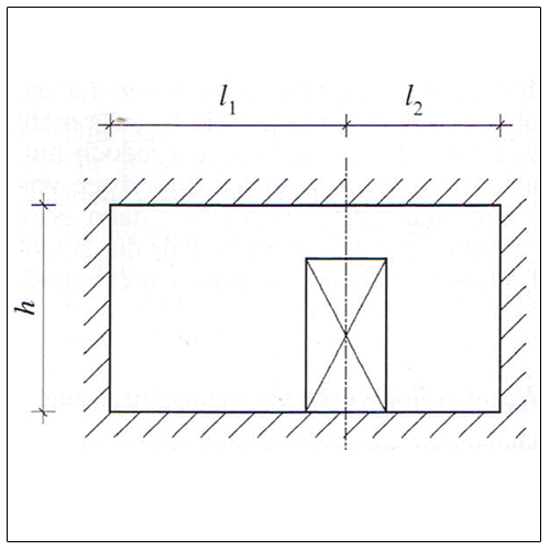
A four-sided wall with a door opening behaves like a three-sided wall with a free vertical edge. The length of the wall is measured up to the door axis.
In the case of walls supported on three sides with an upper free edge, attention should always be paid to compliance with the condition L/H ≤ 2. No door openings can be arranged in these walls. For continuous ribbon windows bracketing the upper edge is recommended. This can be produced, for example, by flat lintels or suitable steel profiles. The partition wall can then be regarded as being held on four sides.
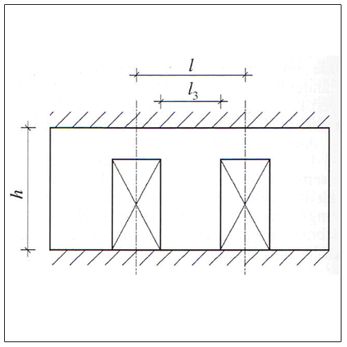
In installation area I, the wall held on two sides at the top and bottom can also be executed. The design of the butt joints has no influence on the wall length, so that the rational design with unmoulded butt joints can be applied. The slimness of the wall is limited to H/t ≤ 30. In addition, for door openings the conditions
L3 ≥ 2/3 • L and L3 ≥ 2/3 • H
must be adhered to.
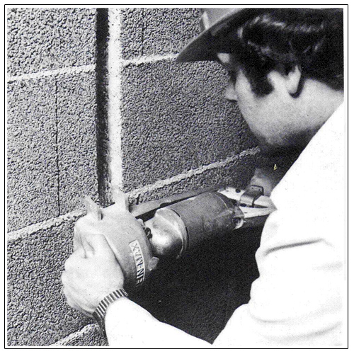
If slots are to be implemented in separation walls, the thickness of the remaining wall is decisive for the determination of the limit values (wall thickness minus depth of slot. The distance of a slot from an opening should be at least 115 mm. Slanted slots should be avoided. Suitable tools which do not destroy the structure of the masonry and which do not endanger the stability of the partition wall must be used for sawing out or milling out the slots. It is recommended to apply fabric reinforcement to the plaster in the area of the slot on both wall surfaces.
Mounting area I
Areas with low numbers of people. Examples: Apartments, hotel, office and hospital rooms and similarly used rooms including the hallways. Separation walls between rooms with a height difference of the floors < 1.00 m.
Walls held at four sides
|
Wall thickness |
Butt joint |
Wall height in m |
||||
|---|---|---|---|---|---|---|
|
2,50 |
3,00 |
3,50 |
4,00 |
4,50 |
||
|
mm |
|
maximum wall length in m |
||||
|
50 |
vm |
3,00 |
3,50 |
4,00 |
- |
- |
|
60 |
vm |
4,00 |
4,50 |
5,00 |
5,50 |
- |
|
95 |
vm |
6,50 |
7,00 |
7,50 |
8,00 |
8,50 |
|
115 |
uvm=vm |
10,00 |
10,00 |
10,00 |
10,00 |
10,00 |
Walls held on three sides, one free vertical edge
|
Wall thickness |
Butt joint |
Wall height in m |
||||
|---|---|---|---|---|---|---|
|
2,50 |
3,00 |
3,50 |
4,00 |
4,50 |
||
|
mm |
|
maximum wall length in m |
||||
|
50 |
vm |
1,50 |
1,75 |
2,00 |
- |
- |
|
60 |
vm |
2,00 |
2,25 |
2,50 |
2,75 |
- |
|
95 |
vm |
3,25 |
3,50 |
3,75 |
4,00 |
4,25 |
|
115 |
vm |
5,00 |
5,00 |
5,00 |
5,00 |
5,00 |
|
uvm |
2,50 |
2,50 |
2,50 |
2,50 |
2,50 |
|
Walls held on three sides, upper edge not held
|
Wall thickness |
Butt joint |
Wall height in m |
||||||
|---|---|---|---|---|---|---|---|---|
|
2,00 |
2,25 |
2,50 |
3,00 |
3,50 |
4,00 |
4,50 |
||
|
mm |
|
maximum wall length in m |
||||||
|
50 |
vm |
3,00 |
3,50 |
4,00 |
5,00 |
6,00 |
- |
- |
|
60 |
vm |
5,00 |
5,50 |
6,00 |
7,00 |
8,00 |
9,00 |
- |
|
95 |
vm |
8,00 |
8,75 |
9,50 |
11,00 |
11,00 |
12,00 |
12,00 |
|
115 |
vm |
8,00 |
9,00 |
10,00 |
12,00 |
12,00 |
12,00 |
12,00 |
|
uvm |
4,00 |
4,50 |
5,00 |
6,00 |
6,00 |
6,00 |
6,00 |
|
Walls held on two sides, on top and on the bottom
|
Wall thickness |
Butt joint |
maximum wall length in m |
|---|---|---|
|
mm |
- |
m |
|
50 |
vm |
1,50 |
|
60 |
vm |
1,80 |
|
95 |
vm |
2,85 |
|
115 |
uvm=vm |
3,45 |
Mounting area II
Areas with larger numbers of people. Examples: larger meeting rooms, school rooms, lecture halls, exhibition and sales rooms and similarly used rooms. Separation walls between rooms with a height difference of the floors ≥ 1.00 m.
Walls held at four sides
|
Wall thickness |
Butt joint |
Wall height in m |
||||
|---|---|---|---|---|---|---|
|
2,50 |
3,00 |
3,50 |
4,00 |
4,50 |
||
|
mm |
|
maximum wall length in m |
||||
|
50 |
vm |
1,50 |
2,00 |
2,50 |
- |
- |
|
60 |
vm |
2,50 |
3,00 |
3,50 |
- |
- |
|
95 |
vm |
4,25 |
4,75 |
5,25 |
5,75 |
6,25 |
|
115 |
vm |
6,00 |
6,50 |
7,00 |
7,50 |
8,00 |
|
uvm |
3,00 |
3,25 |
3,50 |
6,75 |
4,00 |
|
Walls held on three sides, one free vertical edge
|
Wall thickness |
Butt joint |
Wall height in m |
||||
|---|---|---|---|---|---|---|
|
2,50 |
3,00 |
3,50 |
4,00 |
4,50 |
||
|
mm |
|
maximum wall length in m |
||||
|
50 |
vm |
0,75 |
1,00 |
1,25 |
- |
- |
|
60 |
vm |
1,25 |
1,50 |
1,75 |
- |
- |
|
95 |
vm |
2,12 |
2,37 |
2,62 |
2,87 |
6,12 |
|
115 |
vm |
3,00 |
3,23 |
3,50 |
3,75 |
4,00 |
|
uvm |
1,50 |
1,62 |
1,75 |
1,88 |
2,00 |
|
Walls held on three sides, upper edge not held
|
Wall thickness |
Butt joint |
Wall height in m |
||||||
|---|---|---|---|---|---|---|---|---|
|
2,00 |
2,25 |
2,50 |
3,00 |
3,50 |
4,00 |
4,50 |
||
|
mm |
|
maximum wall length in m |
||||||
|
50 |
vm |
1,50 |
2,00 |
2,50 |
- |
- |
- |
- |
|
60 |
vm |
2,50 |
2,50 |
3,00 |
3,50 |
4,00 |
- |
- |
|
95 |
vm |
4,50 |
4,50 |
5,50 |
6,50 |
7,50 |
8,50 |
9,50 |
|
115 |
vm |
6,00 |
6,00 |
7,00 |
8,00 |
9,00 |
10,00 |
10,00 |
|
uvm |
3,00 |
3,00 |
3,50 |
4,00 |
4,50 |
5,00 |
5,00 |
|
When working on existing buildings the different deformations of the frictionally connected components (walls and story ceilings) to be expected in the first few years after the production of the shell construction have generally long abated. The extensive notes for avoiding crack damage in the separation walls of new construction can therefore be omitted.
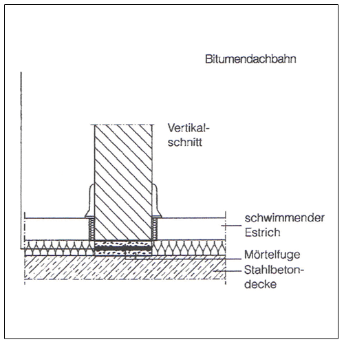
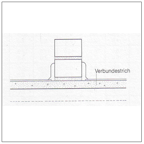
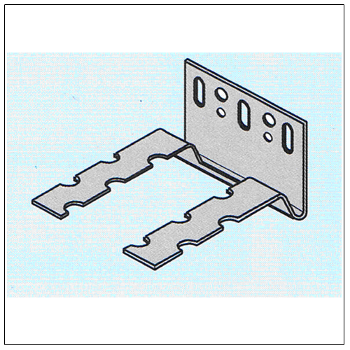
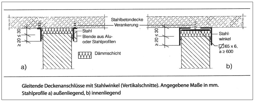
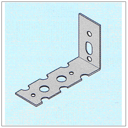
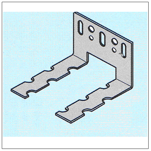
However, it must be taken into account that a separation wall built-in afterwards itself dries out from the construction moisture to the balanced moisture and thereby shortens slightly. For this reason the wall length should not exceed twice the wall height. Furthermore, the vertical wall edges should be elastically connected and grouted and the horizontal wall edges should be supported without constraint. Examples for the formation of the wall edges are shown on the following pictures.
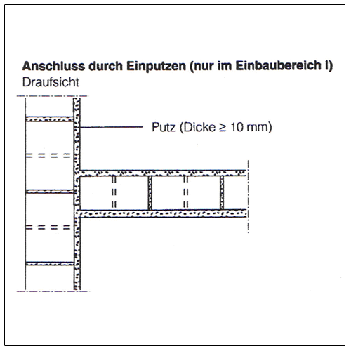
In practice the ceiling connection is generally created by mortaring. This is more likely to be possible for construction on existing buildings than for new construction, as no more constraints from ceiling bend-throughs and resulting cracks are to be expected.
If there are requirements for fire protection for the separation walls, the built-in insulation layer must be non-combustible (Building material class A), have a gross density of at least 30 kg/m³ and the melting temperature must be over 1000 °C. The insulation reduces the flanking transmission for requirements in noise protection at the same time.
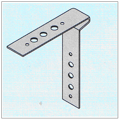
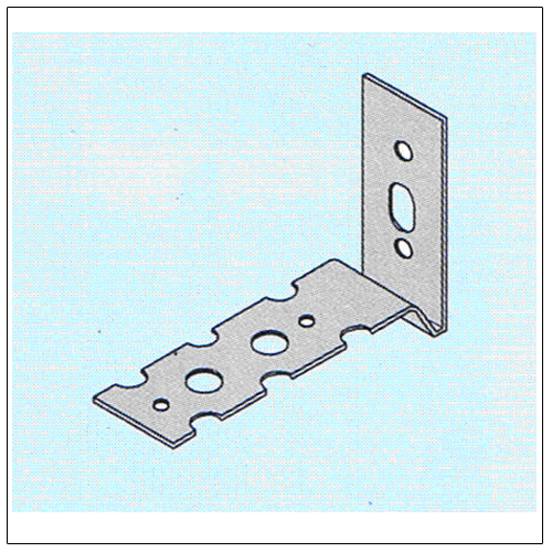
Lightweight concrete blocks are particularly suitable for infilling timber-framed structures. This is proven by numerous built examples in Eifel, Hunsrück and Westerwald, where the masonry has survived decades in this rough climate without damage, even without plaster. In the past it was traditional to attach chamfer strips on the wood and wedge out the blocks accordingly. This is sometimes still desired today for historical preservation reasons. More rationally metal angle brackets are attached to the wood and mortared in the horizontal joint.
Infilling made of light-weight concrete blocks are a load-bearing base for inside or outside insulation for energy renovation of the buildings. Because of the small compartments and the easy workability of the blocks, format 2 DF is typically used.
Expansion joints in the masonry must be incorporated at the same location into the cladding.
- According to DIN 18515-1 the horizontal and vertical distance of field boundary joints should not exceed 3 to 6 m.
- For claddings according to DIN 18515-2 expansion joints are to be aligned at the vertical wall edges, at the upper wall edge and in the cladding surface at a distance L ≤ 2 ∗ H.
The cladding displays a tear-bridging effect, similar to the plaster layer. For reasons of tear safety, the limit recommended for the relationship of wall length to wall height should be maintained with L/H ≤ 2 in the dimensions. For reasons of tear safety of the cladding itself the overlap dimension of ü/h ≥ 0.4 must be adhered to.
Permanently elastic connection joints must be provided at connections between cladding and components with other deformation behaviour (window and door frames, wood, metal and plastic components). They should have a width of at least 10 mm. Fixtures, like windows and doors, must not be attached to the cladding. Attachments of heavy objects are as a rule only possible on the load-bearing base.
5 Literature
German Association for Masonry e. V. (www.dgfm.de): Non-load-bearing interior separation walls made of masonry; Berlin, 4th Edition 2008.
Reeh, H. und Schlundt, A.: Simplified measurement of masonry according to DIN EN 1996-3; Masonry Calendar 2007, p. 227-253.
Detailed information is available in our brochure “Construction on Existing Buildings”.