Walls and wall connections
Wall ends, corners and connection types at a glance
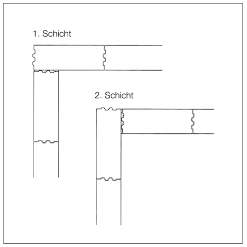
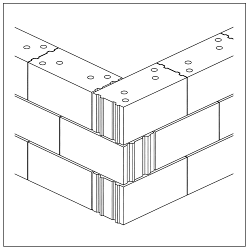
The walls meeting each other at the corners or joints and intersections must be connected such that a secure force transfer is achieved via mutual interlocking. The generally applicable bonding rules for laying brick also apply for these cases.
The following figures show different detailed solutions.
- Corners
- Wall ends
- Integrations
- Butt joint
- Outer wall
- Inner wall
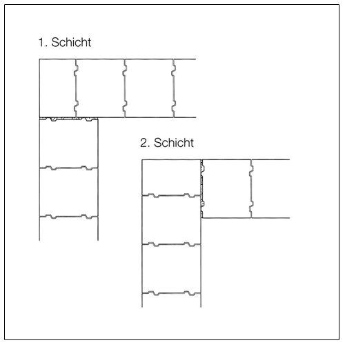
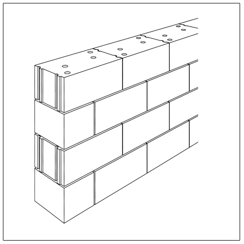
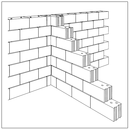
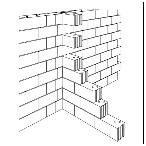
Corner formations
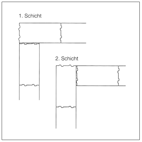
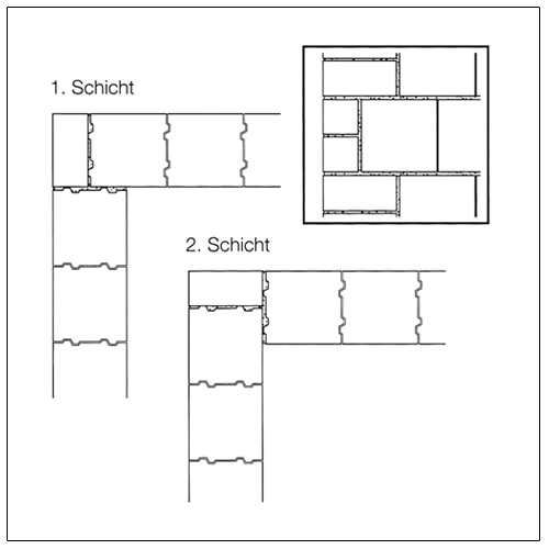
Wall ends
The wall ends for masonry in a middle bond can, in particular for door and window reveal, be supplemented with divisible or cut blocks or with small-format solid blocks. The DIN 1053-1, November 1996 edition also allows bricking up blocks of different height in one layer at these locations, i.e. for 30 type masonry two solid blocks 5 DF may be bricked up on top of each other.
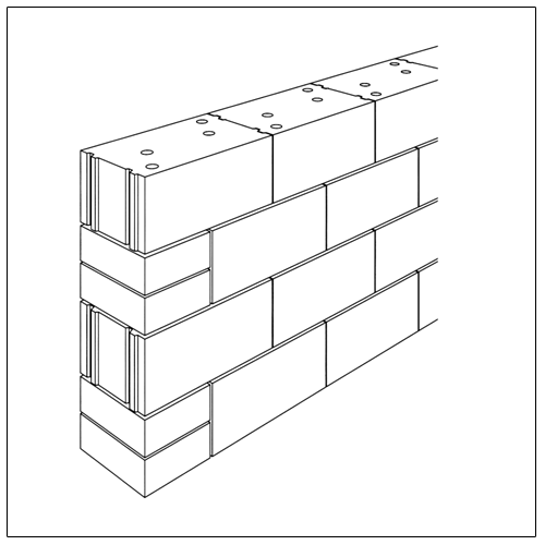
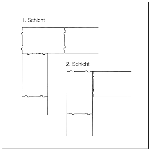
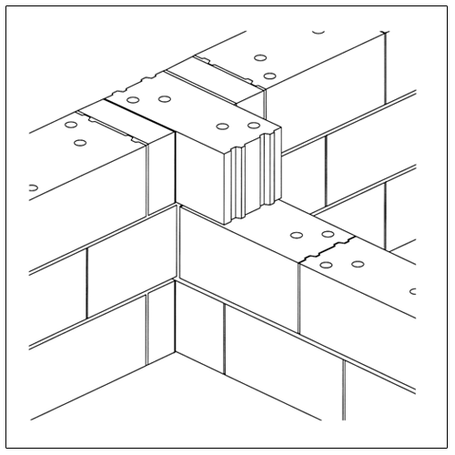
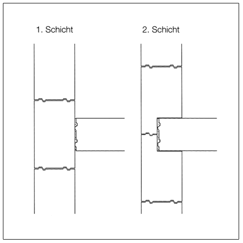
Wall integrations
Wall integrations are often found when connecting load-bearing and bracing walls. Normally the bracing walls should be built up simultaneously with the walls to be braced and bonded with them.
Bracing walls can however also be bricked up later to keep open traffic ways on the storey ceiling. If the two walls cannot be bricked up simultaneously, equivalent measures must be taken, such as horizontal interlocking. While resting interlocking is considered simultaneous bricking up, it usually fails due to lack of space. Bricking up simultaneously or resting interlocking is mandatory for KLB dry masonry.
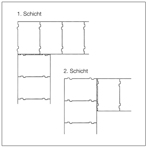
Additional options like
- standing interlocking,
- perforated interlocking,
- storey interlocking,
must only be formed after consultation with the structural engineer. For standing interlocking the following applies: exterior wall braced, interior wall held on two sides, for perforated or storey interlocking: exterior wall or interior wall held on two sides.

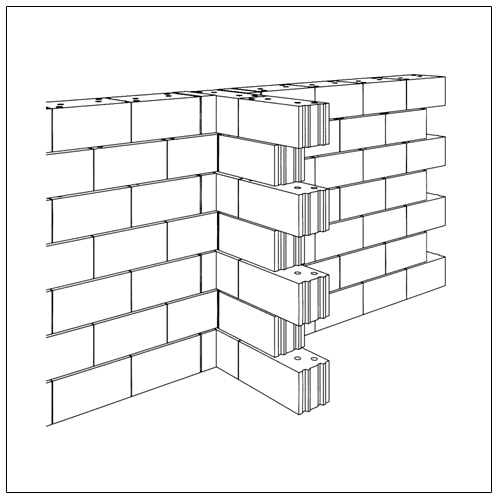
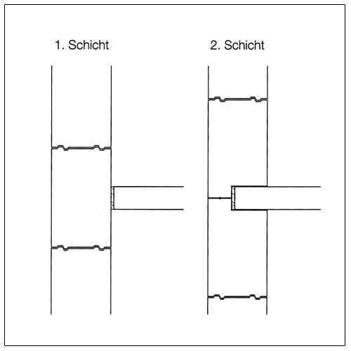
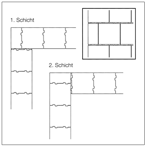
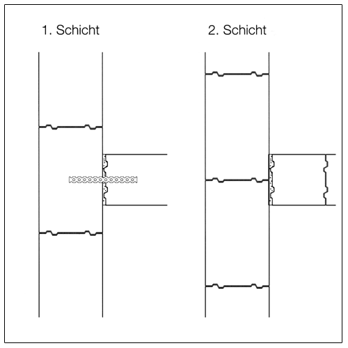
Partial integration of walls
For multi-family apartment houses the exterior walls are typically built out of thermally insulated KLB solid blocks, the apartment separation walls however out of heavy KLB noise insulation blocks. The partition wall can also be partially integrated so that the sound insulation brick does not have to be bricked through to the outside of the building (separating), and a thermal bridge is created.
The exterior walls are for this appropriately cut out in every second layer. In the butt joint area of the partially integrated block thermal insulation should be inserted on the construction site.
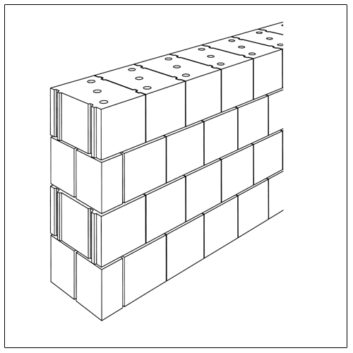
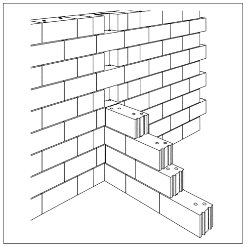
Butt joint
If for rationalising reasons an integration or interlocking is omitted, the connection of the exterior wall to the separation wall must at least be formed using a butt joint. Advantages are
- reduced work time requirement,
- undisturbed work space and free traffic areas,
- problem-free connection of different block formats,
- avoidance of thermal bridges.
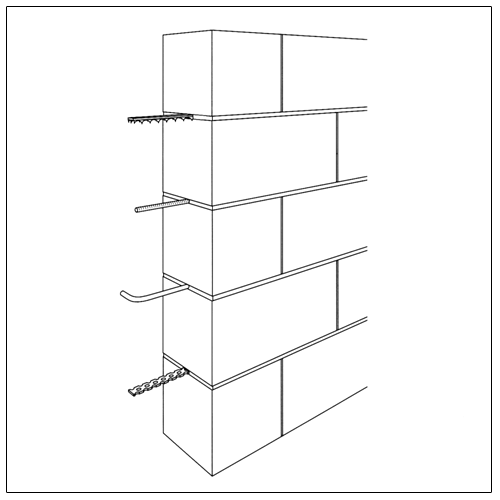
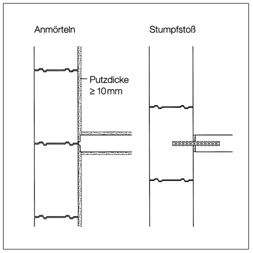
The butt joint must only be used at locations determined by the structural engineer. In a butt joint the connection of the two walls is created by inserting different steel anchors. The anchors are inserted at a minimum in the third points of the exterior wall, in the middle at the location of the cross wall to be erected later, in the horizontal joint mortar when bricking up. After the mortar sets the anchors must be bent down until the cross wall is bricked to prevent injuries. Instead of anchors, which are directly inserted during bricking, systems with anchor rails can also be plugged in afterward. The anchors are then not hung onto the anchor rail until the cross walls are bricked and pushed parallel to the respective horizontal joint into the mortar. For the anchors, anchor form, anchor intervals, type or mortar and mortar group static documentation is required.
For structural and noise technology reasons the butt joint must be mortared vertically interlocking.
Connections of non-load-bearing exterior walls
Non-load-bearing exterior walls are used in infill masonry. Frame and cross-wall constructions made of reinforced concrete or steel as well as for half-timbered construction out of wood. The infill masonry can be single or double shelled. For single plastered walls the minimum thickness is 11.5 cm, for single shelled exposed brickwork (with shell joint) 31 cm. For double shelled masonry both shells must be at least 11.5 cm thick.
According to DIN 1053-1 the static proof can be omitted if the walls are rectangular, e.g. are held by interlocks, offset or anchors, and mortar of mortar group II a or III is used. The connection means must comply with the standard safeties.
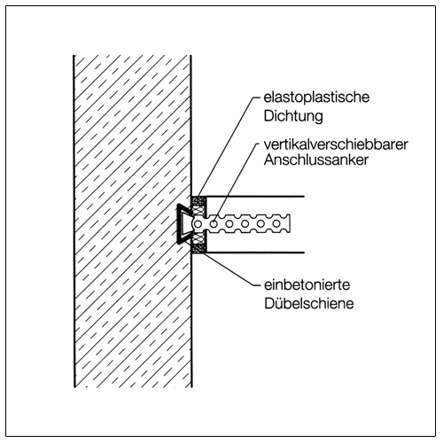
The connections must be able to handle the wind loads as well as the influences due to deformations of the adjacent constructions. Depending on the requirements the connections can be implemented rigid or flexible.
The rigid connection, e.g. via anchor, mortaring or interlocking should only be used if no large constraints and deformations are to be expected from the block material and the adjoining support construction. Flexible connections, laterally and/or above, should be built via grooves or steel profiles. The walls must be backfilled with mineral fibre strips or equipped with flexible layers on the friction surfaces.
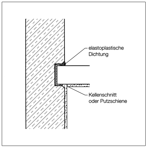
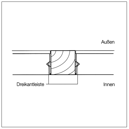
When connecting masonry to supports cracks appear in the boundary area due to constraints. The boundary surfaces must therefore be covered with a reinforced plaster, or a visible joint should be formed. The latter solution is always necessary if larger deformations are to be expected. The joints must be sealed against moisture penetration.
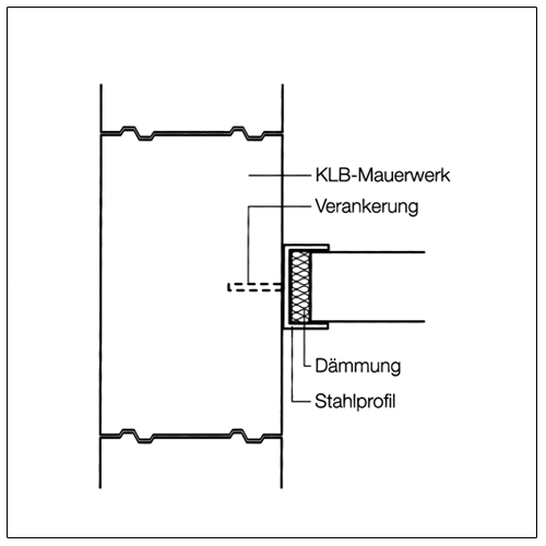
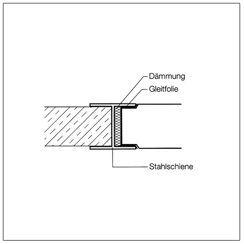
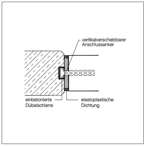
Connecting to steel supports is easy if the clear dimensions of the I-profile are selected appropriately for the block widths, so the block is covered from the profile and can glide within the profile. For steel concrete supports the masonry can be anchored in the horizontal joints by gliding over dowel rails. For a rigid connection you mortar interlocking against the support.
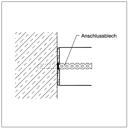
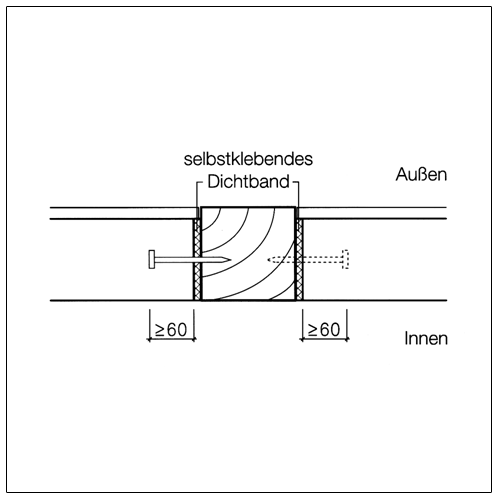
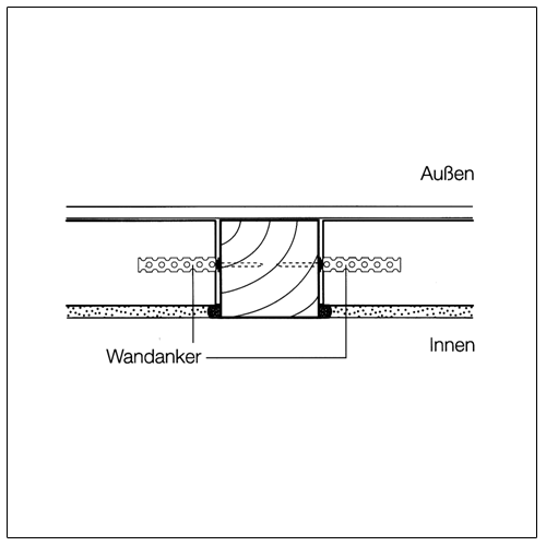
For connecting to wood supports (half-timbered) the horizontal connection can be implemented by using galvanised nails. The vertical hold is given by e.g. nailed on wall anchors (anchor flashing). The moisture protection and tear hazard must be taken into account via appropriate sealing measures (self-adhesive sealing ribbon, elastoplastic seal etc.).
Connections of non-load-bearing interior walls
Non-load-bearing interior walls or non-load-bearing interior separation walls are usually implemented in masonry as light-weight separation walls within the meaning of DIN 1055. Implementation guidelines and requirements according to DIN 4103.
The interior non-load-bearing separation walls should not be installed until after completion of the shell construction as at this time a large part of changes in the shape of the support structure construction caused by the shell structure are already completed.
Non-load-bearing separation walls do not reach stability until connected to the adjoining components. For these connections the deformations of the adjoining components to the separation wall must be considered. Deformations can be mostly prevented via flexible connections. Tear-free length approx. 2 times the clear height. Expansion joints must be planned for in the area of the door support, or storey-high door elements must be built in.
Rigid connections are created by interlocking, mortaring and anchor flashing or integrating steel inserts. Rigid connection by mortaring are common in practice, but should be limited to apartment construction or used for walls for which no or only minor constraint forces are to be expected from the adjoining components on the separation wall, and at least one three-sided bracket, i.e. on top and bottom as well as a vertical edge, is given.
A rigid ceiling connection can be created via mortaring. The deformation influence of the adjacent ceiling is minimised by inserting a 1 cm hard foam strip. When plastering, both components must be separated through a furrow, so later on no jagged cracks show in the transition area of the ceiling to the separation wall.
Flexible connections should always be used if deformation is expected through unplanned force introduction. They are created by aligning profiles and grooves. The joints must additionally be filled for sound and fire protection reasons with mineral fibre insulation materials.
The placement on the ceiling (base point) occurs with a floating floor by placing the wall directly onto the load-bearing ceiling. For large span widths the wall must be bricked up on sanded cardboard or another flexible foil to prevent a tearing of the bottom block layer if the ceiling bows. For a bonded floor proceed the same way, however, the wall can also be mortared directly onto the floor.