
Exterior wall constructions
Structure of different types of walls with KLB masonry
Walls are built as single or double shell masonry depending on the demands placed on them. Single shell masonry consists of a single masonry shell, which can be plastered or not. Double shell masonry consists of two masonry shells, which are either connected by a shell joint over the entire masonry section, or are separated by an air layer, with or without additional insulation layer.
- Single shelled
- Double shelled
- Wire anchor
- Support and propping
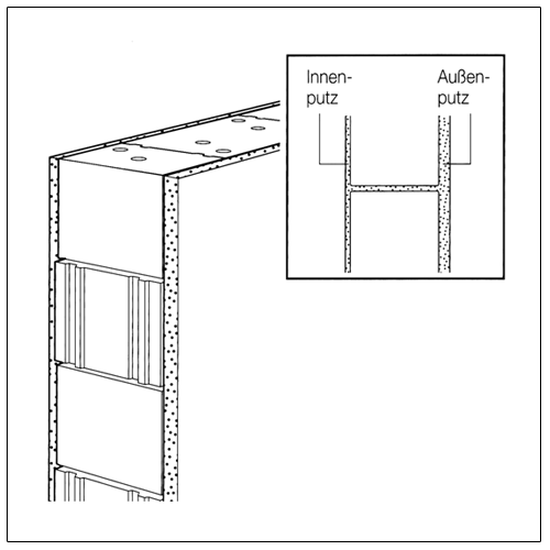
Masonry plastered on both sides
made of KLB blocks is always single block masonry. The entire wall thickness is uniformly able to bear loads. For thermal and noise insulation the entire masonry cross section is also effective. For plastered exterior walls a minimum thickness of 17.5 cm is required.
Exposed brickwork
For reasons of driving rain safety, exposed brickwork for apartment buildings must consist of at least two block rows per layer, which are separated by a full joint longitudinal joint of ≥ 2 cm. The use of KLB wall building material for exterior exposed brickwork is not common. The wall surfaces exposed to weather must be provided with a water repellent colour or colourless silicon paint. Interior exposed brickwork, e.g. in stairwells should at least be smoothed or plastered on a wall side for noise protection reasons.
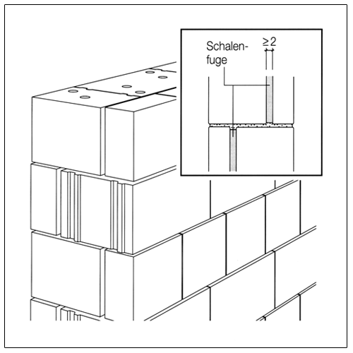
Masonry with shell joint
Masonry with air layer
consists of an exterior faced wall shell, which is directly connected to the inner load-bearing masonry shell. The shell joint has to be ≥ 2 cm and thereby works as a block against driving rain. It is recommended to plaster the exterior side of the load-bearing shell before bricking up the faced brickwork, or to brick up both shells at the same time and to cast the shell joint layer by layer with slowly flowing mortar. Both shells must additionally be connected with wire anchors. Note that with different materials and different thermal conductivity capacities stress leads to construction damage. From a building physics perspective (heat and sound protection) KLB masonry can be built monolithically without problems, i.e. single shelled with plaster on both sides. The creation of double shelled masonry is often dependent on the region and the landscape, because the facade is not plastered but faced for weather reasons.
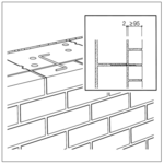
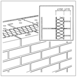
has very good building physics characteristics with proper implementation. The outer shell keeps driving rain safely off the inner one. Different material stresses do not lead to problems. The interim air space has to have connection with the outside air through intake and outtake openings (down below ventilation blocks, above open butt joints), so continuous ventilation guarantees the removal of water vapour. The air layer must be implemented ≥ 60 < 150 mm thick. The outer shell must be mortared very carefully, so no mortar falls into the air shaft. Both shells must be connected by wire anchors. The wire anchor must be installed with a drip disc according to the regulations.
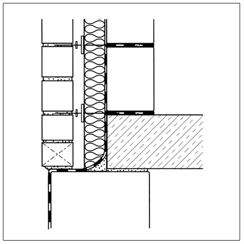
Masonry with air layer and insulation
Masonry with grain insulation
is processed like double shelled masonry with an air layer. However, the air shaft only has to be ≥ 4 cm thick. Since the total distance between both masonry shells in general must only be 15 cm, the insulation thickness is limited to 11 cm. The wire anchor is to be built in the same way. In addition to the drip disk it should, in particular for fibre insulation material, have material clamp plates. The interim air space has to have connection with the outside air, so continuous ventilation guarantees the removal of water vapour.
consists of an inner, load-bearing and an outer non-load-bearing masonry shell between which up to 15 cm insulation material is inserted without interim air space. In addition to panel-shaped insulating materials, suitable and approved fillings are particularly suitable as insulating materials. The insulation layer is in contrast to double shelled masonry with air layer subject to higher moisture demands. Both shells must be connected by wire anchors. Below drainage openings are to be planned in, so a possible moisture occurrence can be drained.
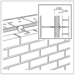
Wire anchor
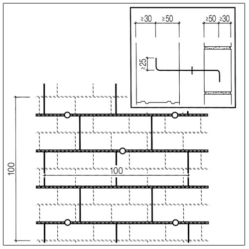
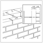
For all double shelled constructions the outer shell is not stable until the connection of both shells using wire anchors (number and item/m² according to DIN 1053-1) is made of non-rusting steel. For 5 anchors per m² the vertical distance of the wire anchors should be ≤ 50 cm, the horizontal distance ≤ 75 cm.
At all free edges (window and door openings, building corners, along the expansion joints and at the upper finish of the faced shell) at least 3 anchors per running metre of edge length must be integrated additionally.
If the wire anchors are embedded in light-weight mortar, LM 36 is required. With LM 21 a different type of anchor must be chosen.
For other types of anchors a test certificate is required for proving the bearable forces and deformations.
The anchors are inserted when bricking up the load-bearing back wall shell. For later installation, such as for KLB dry and KLB flat block masonry, wire anchors can be plugged in. For this approved dowels must be used.
Support and propping
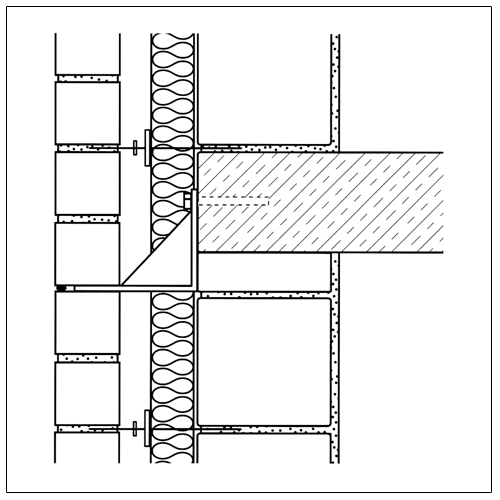
According to DIN 1053-1, the facing shell, which can also be designed as a plastered facing shell, must be supported over its entire length over the entire surface and safely. It makes sense for this support to be placed on the foundation or the outer wall of the cellar. At the base point of the air layer between the interior and faced shell the interior shell and the adjacent storey ceiling respectively must be protected against moisture. This also applies to window and door lintels as well as in the area of window sills.
- In case of interrupted support, e.g. on consoles, all blocks must be supported on both sides in the collecting level. The minimum thickness of the exterior shell is 90 mm.
- Exterior shells of 115 mm thickness should be propped at height intervals of about 12 m. They may extend up to 25 mm over their support.
- Exterior shells < 115 mm thickness must not be extended higher than 20 m over premises and must be supported at height intervals of about 6 m.
The industry delivers different prefabricated supporting constructions, such as
- individual consoles for supporting finished part lintels, closed wall areas,
- corner consoles for propping pillars and outside corners,
- console angles for supporting over openings, expansion joints.
As a rule they should be manufactured from non-rusting steel. Supporting constructions are preferably attached to the ceilings or lintels. The screw connection should be carried out with heavy-duty dowels. Make sure that the rear ventilation of the faced shell is not significantly obstructed or even disrupted. Below interim supports the faced shell must have enough expansion leeway so temperature expansions do not cause obstacles and material flaking.
The props should be chosen such that they are not visible from the outside, so by joint formation, for example. Above door and window openings this is possible if the blocks of the jack arch are bolted with the console angle.
In the exterior, shell vertical expansion joints (in particular at the building corners) must be arranged. Their distance intervals depend on the thermal (climatic) demand and the type and colour of the facing material. For facing over several storeys and a corresponding number of openings the different deformations of both shells must also be observed. Expansion joints must be permanently sealed with suitable material.